This is part of a series of articles about the Parrot Anafi, we will cover dismantling, repairing and modding.
For this this article we will be modifying the Skycontroller 3.
On Android phones the Parrot Anafi remote controller (the Skycontroller 3 or SC3) charges the phone that is plugged in to it – and this annoys me!
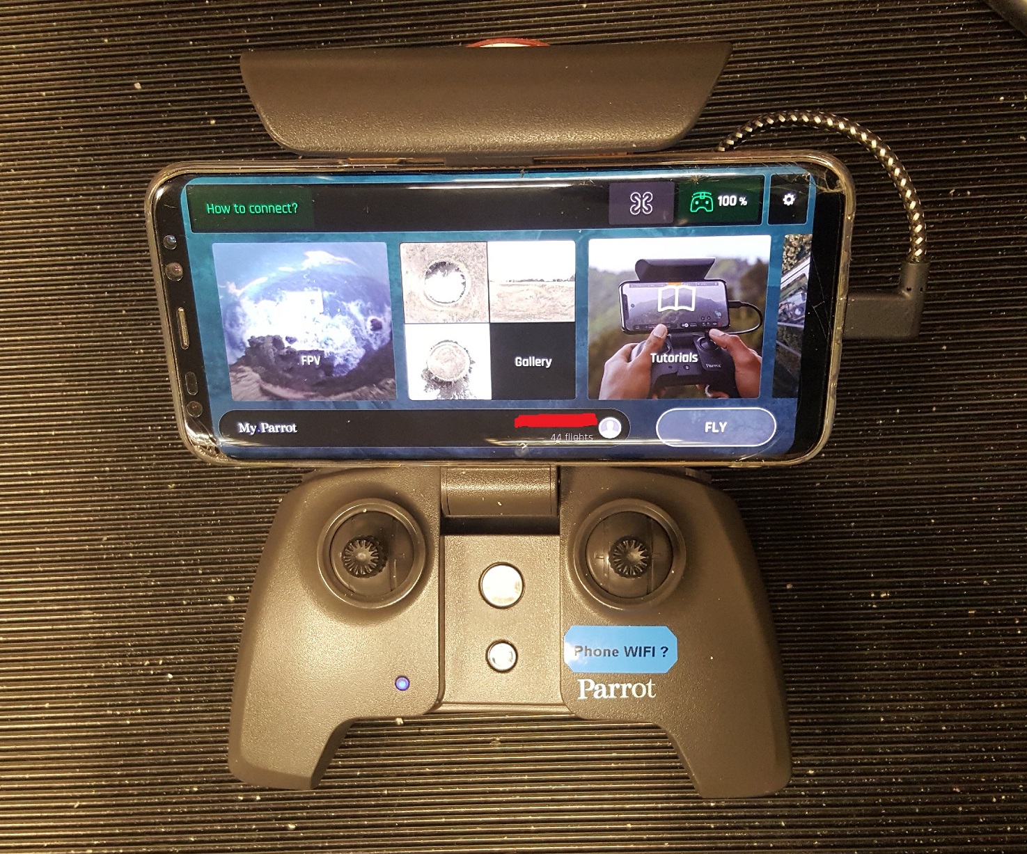
The SC3 internally has an single cell 18650 Li-Ion battery as its power source – rated at ~ 2500mAh. Meant to power the controller for around 4-5 hours, however when connected to an Android phone this time becomes more like 2 hours. In reality I have found that the controller can use 50% of the battery charge with around 30 minutes of use when connected to my Samsung Galaxy S8 Plus.
My drone kit has 3 Anafi batteries each giving me around 25 minutes of flight – and I would say that the SC3 battery level would fall to dangerously low levels when flying all 3 batteries on the Anafi.
Taking various measurements when I have either my Samsung Galaxy S8+ or Galaxy S6 Edge connected they are drawing around 500mA at 5V from the SC3. Which is quite a large current considering the single cell 18650 battery supplying it.
Simple way of stopping this is cutting the 5v USB line and inserting a resistor to limit the charge current.
Few people have done this but they have made the break within the USB lead between SC3 and phone. I don’t like this method as a) the USB cable is a wear item, and b) I have USB-C and Micro USB connectors on my phones, which require different cables.
Best method would be to modify the SC3 itself!!
The Mod
You will need:
- Soldering iron & solder
- Resistor (value discussed below)
- Torx driver T6
- Torx driver T4
- Tweezers or small jewellers screwdrivers
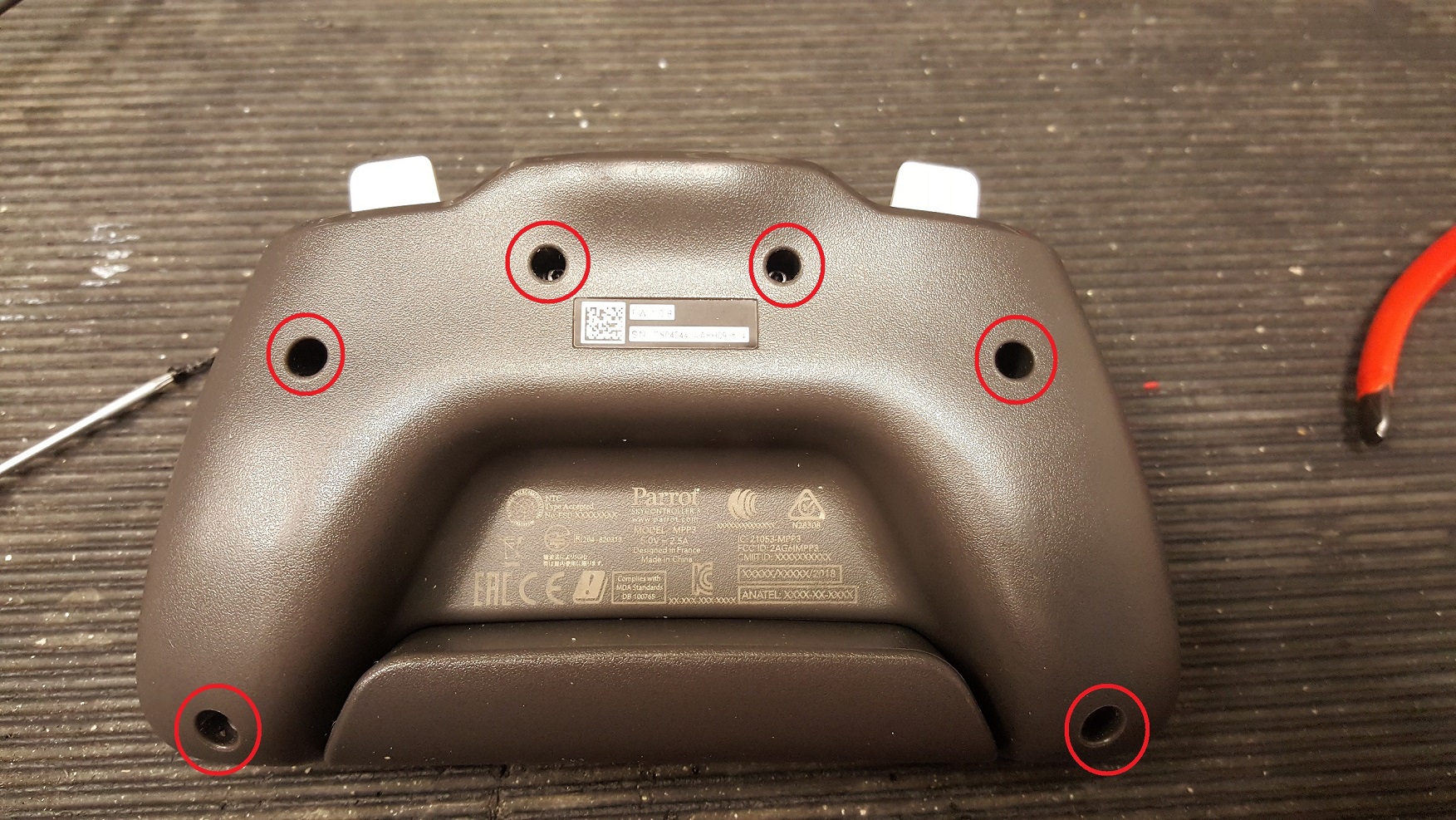
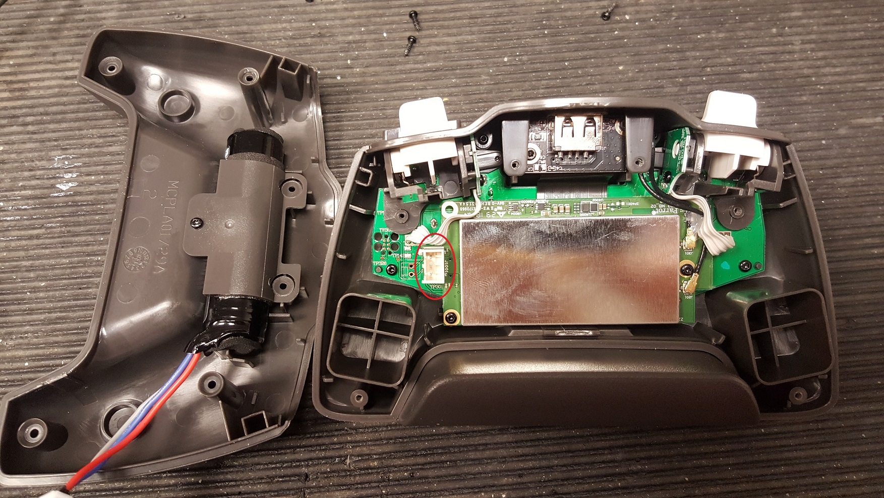
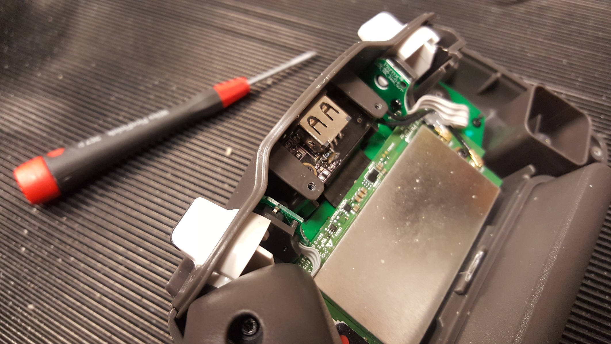
1. Remove the back cover of the SC3, undo the 6x Torx T6 screws and lift away the back. Press the latch on the battery connector and disconnect.
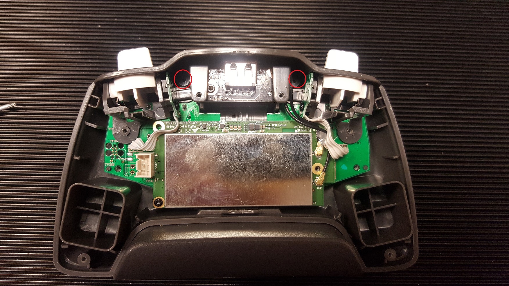
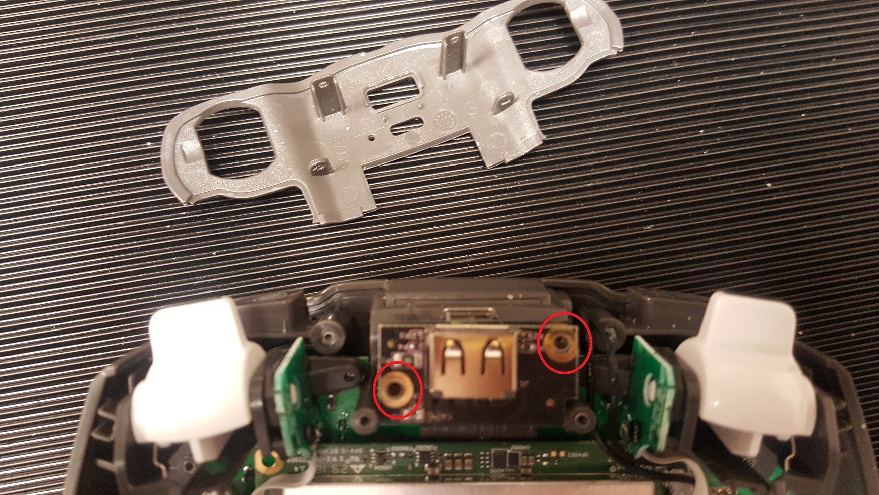
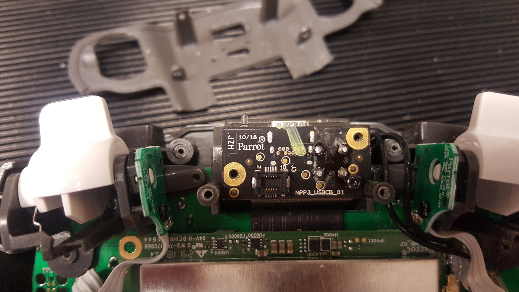
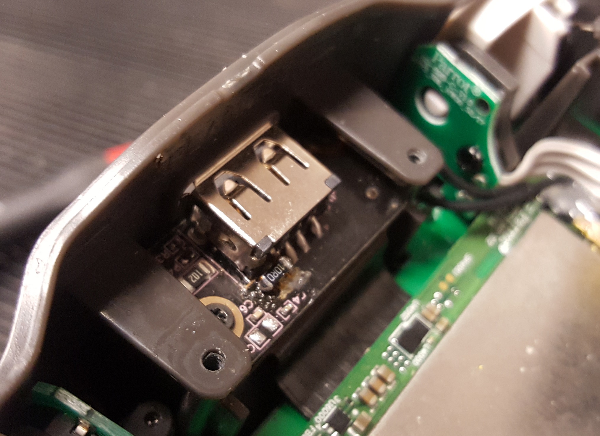
2. Remove front face plate by undoing the 2x Torx T4 screws and lift the face plate out. Undo the 2x Torx T6 screws holding the USB daughter board, then gently lift the USB board up and out.
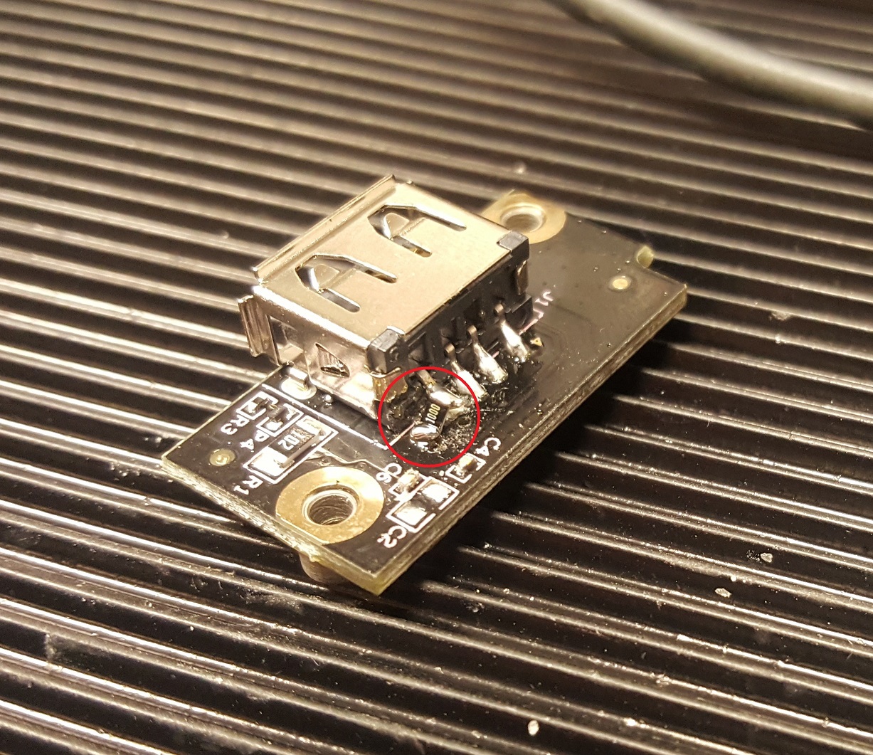
3. Using the soldering iron, reflow the solder on the USB connector 5v line and lift the pin away from the solder pad. Do this very carefully as you can damage the solder pad. Make sure the solder has fully melted on the pin before trying to lever it up.
4. Solder in a resistor between the lifted 5v pin and the solder pad below it. My final resistor was an 1206 sized surface mount resistor, but a smaller 0805 size SMT will be ok, and so will a standard through-hole resistor. We go over the resistor value below.
5. Re-assemble the SC3 reversing the steps above. Done!!
The Resistor
Brief technical explanation about the USB port on Android phones.
The phone uses the 5v line as a source of power to charge the phone and it is also used to detect accessories. By introducing an resistor in to the 5v line, we will be reducing the voltage presented to the phone especially if it attempts to enter a charging state. The final resistor value is going to be a balance between limiting the charge current and the phone reliably detecting the SC3.
I tested a few values to see how they worked with my USB-C port Galaxy S8+ and the micro USB port Galaxy S6 Edge. Values tested were 100, 47, 33, 5 Ohms.
During my tests – values above 33r worked fine with my SGS8+ but the SGS6Edge would not detect the SC3. At 33 Ohm the SGS8+ still worked ok, however I got the odd charging screen pop up during use, as well as continued issues with the SGS6Edge.
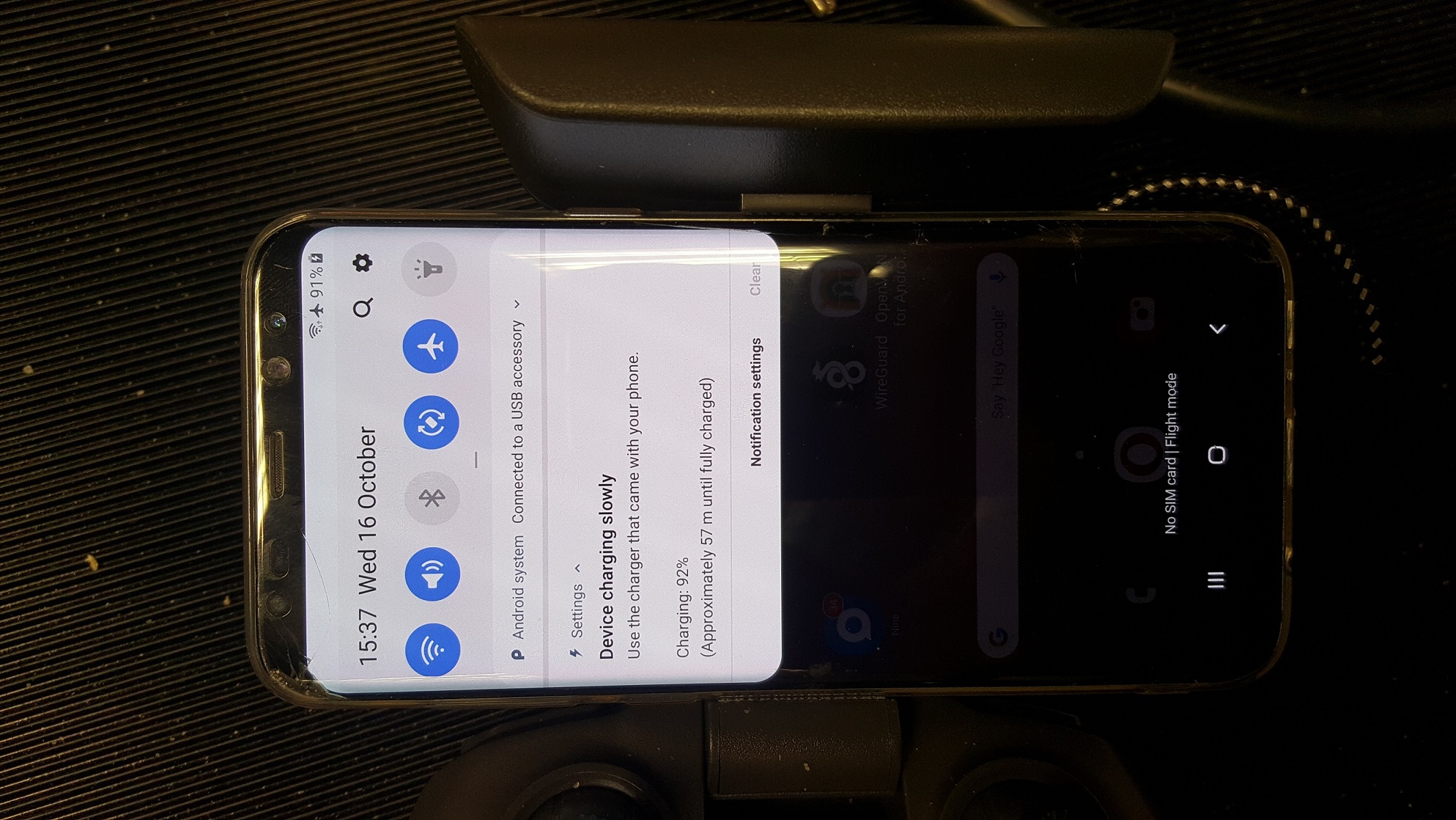
Next I tried a low value 5 Ohms (well 2 10 Ohm resistors in parallel). This worked well with the SGS8+ no random charging pop-ups, and the phone went in to slow charge mode – which meant it was charging at 100mA rather than standard charging at 500mA. The SGS6Edge worked with no issues, that went in to charge mode drawing around 150mA.
I decided to stick with the 5 Ohms. While it does not stop the charging – it did reduce charge current to around 100mA (150mA on the SGS6Edge), this is a big reduction from the 500mA being drawn from the SC3. Now the SC3 battery level drops around 15% per flying session rather than 35-45%.
If you were worried about the power dissipated by the resistor. The voltage drop across the 5 Ohms was 0.65v with the SGS8+ and around 0.8v with the SGS6Edge. So quick power calculation shows that power dissipated by the resistors will be 65mW with the SGS8+ and 120mW with the SGS6Edge – the resistors I used have a rating of 500mW (technically as I am using two in parallel the max rated power would be 1 Watt combined), so nothing to worry about here.
Conclusion, great success and well worth doing.
cool we missed u Tarkan