Feature Set
When I had a dream about making a GPS device for my Nikon, I had this idea that if I can make it small enough maybe I can have the whole unit directly attached to the camera with no cables. I had several other criteria to meet, the unit was to be powered by the camera and also to be fully integral to how the camera behaves in terms of power control. I did not want a separate on/off switch and the GPS device had to enter and leave sleep mode as and when the camera did.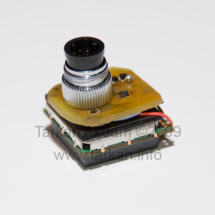
With my design I wanted to create something which is plug and play with a simple plug and forget attitude. I want it to work without having extra buttons, switches or usage constraints. I want to pickup the camera and take a picture knowing the GPS position has been recorded.
This also means this thing has to be tiny and when I mean tiny I mean tiny. As you will see my early prototype was so small it was directly mounted on the 10pin Nikon connector with no cable, but this was not viable as it meant difficulty pressing the Lense release and flash button.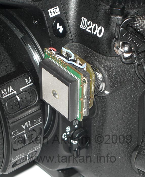
Performance this is important – I expect it to work inside buildings and other difficult locations, my little TomTom sat nav unit can – so should mine.
Finally, power or lack of. The unit will be running off the camera battery, so power requirements need to be small and some very aggressive power saving techniques need to be employed. As stated to be aware of the power savings of the camera.
Required feature set :-
- Plug and play
- Plug and forget
- Miniature and discrete
- Low Power
- High Performance
- Software driven intelligent device
First thing I obtained a Nikon 10-pin connector and slowly checked and measured each pin function, I created a chart showing the various states with the measured voltages. The states of interest are camera on , off , meter on, meter off (sleep mode) I checked the pins to see what was going on using the excellent chart hosted on Peter Miller’s website (link above).
Next major thing was to get a GPS module, I was on the look out for a tiny module which had excellent specs while still having plenty of power saving features – I knew of this Finnish company Fastrax, quick look over their website revealed the IT321 gps module measuring a eye-watering 14mm x 10.4mm x 2.3mm – Tiny. The great thing with this module was that it is based on the SIRFstar 3 gps chipset, so performance is guaranteed to be great!!
Finally I could look at the gps antenna – I personally believe the antenna makes or breaks gps units. Companies spend lots of money getting the antenna right and it is normally approached on a holistic basis – with the antenna designed once the rest of the device has been finalised. Most people tend to use patch antenna for gps devices, these are squarish ceramic based antenna. These work really well however they do have some drawbacks. First is detuning – when anything is placed near the antenna it detunes from its operating frequency, even plastic or human skin. Secondly, ground plane requirements – patch antenna to operate correctly need a large ground plane (large piece of copper), so for my project I calculated I would need a 20mmx20mm patch antenna to achieve the performance I was looking for the minimum ground plane would need to be at least 50mmx50mm – this is just too large for my needs.
So I started to look at helical antenna, they are much more compact and have much less detuning effect and the ground plane requirements are non-existent. I managed to track down an antenna made by Sarantel – it is small measuring just 13mm diameter x 15mm width and 49mm long with a waterproof rubber sleeve protecting the antenna element. The good stuff does not stop there – it also includes a low noise low current 24db gain amplifier. The other thing I have not mentioned pickup pattern – the direction the antenna is most efficient in. Well the helix has a 165degree cone shaped receiving pattern which is perfect for my needs.
It was coming together well due to the size of antenna and gps module – I found that I could piggy back the gps module on to the antenna, so I now had to design my controller board to piggy back on to the antenna. This was going to be interesting as my circuit had to measure 18mm by 12mm and thin as possible.
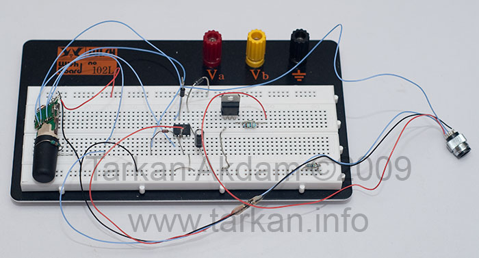
My attention was now switched to designing my controller circuit – so we know it has to be small and intelligent which means only one thing microprocessor, my requirements are simple so I selected the lowest power 8bit processor I could find – Microchip’s Pic12f629, it also satisfies my size requirements as it is packaged in a 8pin SMT SOIC. The remaining components would deal with power supply and level shifting between the 1.8v Cmos output of the GPS module to the 5v TTL input of the Nikon Camera.
Hi – Any further developments? I am interested in building one of these and have some limited SMD experience. Are you planning to release a kit or plans+software?
Great project!!
Hi. Some News about this great module?
Hi,
Nice work. Just one question.
Why do you use a controller board. Most common GPS modules has a configurable RS232 port. and Nikon DSLR accepts RS232. You just need a level converter!
Thank
Hi, looks interesting, can you tell me where yto get the nice 10-pin conecter you have used in your early prototype?
Thanks a lot!
Great work. I have interested in a complete unit for my Nikon.
hi tarkan,
great work. My D700 ;-)) and I are interested in a complete unit.
Didi
connect nikon to garmin using bluetooth, please see http://julianbiotecc.spaces.live.com/?_c11_BlogPart_BlogPart=blogview&_c=BlogPart&partqs=amonth%3d4%26ayear%3d2010
Any News on the kits ?
That does surprise me by fast aquasition and I am quite satisfied with this Eztagger GPS.
The Easytagger is cool. I got it for a week now and used it for almost everyday. I do enjoy the trails. It shows every detail of my movement.