Controller Board
As you can see I managed to fit my controller design on to a pcb measuring 18mm by 12mm on clad board measuring 0.4mm thick. This will fit perfectly on to the Antenna module. As the size of the board was so small my pcb fabricator had to make it on a much larger piece hence why I ended up with 60 boards!!!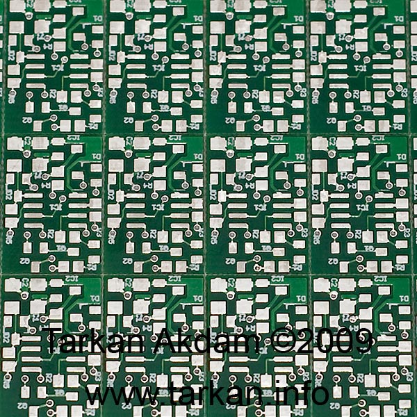
The circuit is pretty simple – there is 4 wires connecting the board to the camera, these are for power, gps data, and shutter button. On the other side 7 wires connect to the GPS module, these are for the power and data signals.
The design uses a total of 13 SMT components, the main active parts of the circuit are the power regulator which converts the 5v from the Camera to 3.3v required by the mcu and gps module – this component (MCP1701A) was chosen for the lowest possible quiescent current less than 2uA. The Microchip PIC12F629 micro-controller running my custom software (more on that later..), and two digital transistors used to level shift between the different data lines.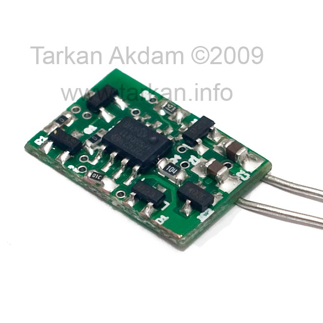
The remaining passive components are for smoothing and signal pull-up.
Putting it together
So the circuit board, gps module and the antenna were put together – and using some tiny Teflon coated cable I connected the gps module to my controller board. I used a tiny piece of solid microwave cable to connect the output of the antenna to the RF input on the GPS module.
As you can see from the pictures – it is small and very neat looking package. Final step was to solder up the 4 wires coming from the Nikon – I made my own cable from the Nikon connector to my gps unit.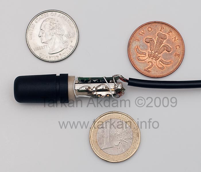
I have placed some international coinage in the photos to give you a sense of scale.
Software
I designed my circuit so I could program the micro-controller in place – technical name for this is in-circuit programming. This was important as I can update or change the software if it was not operating how I wanted it to.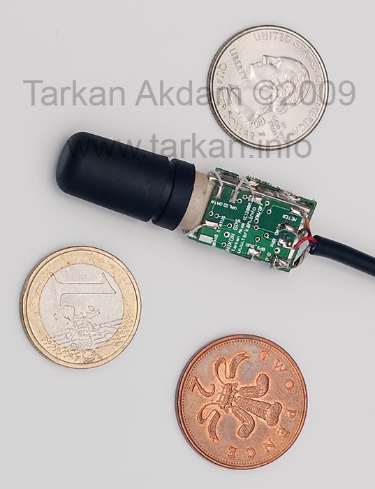
The purpose of the software was to carry out the following functions :-
Main function
- Whenever the camera shutter button is half pressed (AF / Metering activated) the controller is to wake up the GPS module and start sending gps position data to the camera
- After 6 seconds from the last press of the shutter button the controller would stop sending gps data to the camera this would allow the camera to enter standby. Nikon stops the camera going in to standby mode if anything is attached to the serial data input line, causing the camera battery to run down very quickly.
- The controller will check the data stream to make sure we have a good positional fix, if not it will keep the gps module awake till we have achieved a better fix then go to sleep – camera is not aware of this part as the data line to camera has been disconnected by the controller.
House keeping function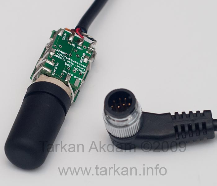
- House keeping function happens regardless of the camera state. On initial power up the controller will wake up the gps module and start acquiring satellites to get an accurate positional fix. The controller would keep the gps module awake till at least 5 satellites are acquired and set.
- The house keeping will also wake up the gps module every 8 hours to refresh the satellite table and update the position if location has changed quite drastically.
There is a timeout of around 3 minutes – so if the gps unit is say stored away in a camera bag then it is unlikely the gps would acquire any satellites so after 3 minutes the controller board will give up trying and go back to sleep. This should stop the gps unit running down the camera battery in futile situations trying to get a positional fix.
So after going through several versions I managed to iron out all the bugs and got the program doing what I wanted. After successfully burning the MCU, I can move on to testing.
Hi – Any further developments? I am interested in building one of these and have some limited SMD experience. Are you planning to release a kit or plans+software?
Great project!!
Hi. Some News about this great module?
Hi,
Nice work. Just one question.
Why do you use a controller board. Most common GPS modules has a configurable RS232 port. and Nikon DSLR accepts RS232. You just need a level converter!
Thank
Hi, looks interesting, can you tell me where yto get the nice 10-pin conecter you have used in your early prototype?
Thanks a lot!
Great work. I have interested in a complete unit for my Nikon.
hi tarkan,
great work. My D700 ;-)) and I are interested in a complete unit.
Didi
connect nikon to garmin using bluetooth, please see http://julianbiotecc.spaces.live.com/?_c11_BlogPart_BlogPart=blogview&_c=BlogPart&partqs=amonth%3d4%26ayear%3d2010
Any News on the kits ?
That does surprise me by fast aquasition and I am quite satisfied with this Eztagger GPS.
The Easytagger is cool. I got it for a week now and used it for almost everyday. I do enjoy the trails. It shows every detail of my movement.