The Why
I have been busy as you can tell form my lack of posting :), but to ease myself back in to blogging I thought I would start with something simple.
Recently I built a strong room in my garden shed to store my tools, etc. I got stuck thinking about the locking arrangement for the strong room door. I did not want to use a key as it would be easy to forget to lock it or just not having the key with me while out in the garden requiring a trip back to the house.
The shed is wired up to the main house alarm and has its own keypad, so I thought why not make an electronic locking mechanism which could be controlled by alarm – this way when the shed is disarmed the lock can automatically unlock the door.
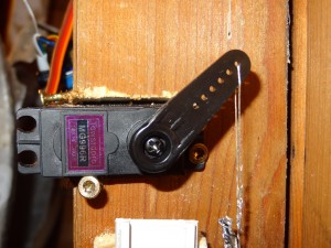
Well I got a couple of dead bolts and 2 metal geared RC servos to move the dead bolts, then I set about designing a circuit to control the servos – so I need a circuit which would move the servos between two positions and it would need to be programmed with the relevant positions, and finally be able to receive a signal from the alarm to move the servos to the lock or unlock position.
When I was finished, I was so impressed by how simple and elegant – I thought others would find it useful…..
The Circuit
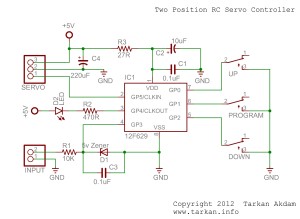
The final circuit is very simple – 10 components and 3 switches which are for programming the two positions.
As you can see a very simple circuit. It uses a very cheap Microchip PIC12F629 processor and a handful of capacitors and resistors – you will need a 5V supply to run the circuit which will also be used by the Servo Motor.
The input trigger can be anything from 3V to 30V.
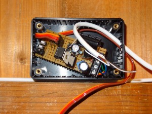
I have not included a PCB design as it is far cheaper and quicker just to make it on some veroboard/stripboard. Below you can find the HEX file for the Pic chip and the original source code in PICBASIC if you want to see how the program works or as a starting point for your own design and modifications.
Operating Instructions
Once you have a made the circuit and programmed the PIC chip. Connect the RC Servo and power up the circuit. If everything is ok the servo will probably move.
The LED should start to flash, this is the heartbeat to show you the processor is running ok.
Now press the program button – LED should stay on constantly – you will have to hold this down if you have not used a toggle switch. Then press Up or Down to move the servo, when the servo is in the desired position – wait till the LED rapidly flashes which tells you the positions has been stored in to the internal Eeprom.
Next, apply your trigger voltage to the input and repeat the above programming instructions for the second position.
Once both positions are programmed, when the trigger voltage is removed the Servo should move to the first position and when voltage is applied it will move to the second position.
Things to know
The circuit does not provide any holding force – so once the servo moves to the desired position after a couple of seconds the circuit disables the servo.
This means if there is any return force being applied to the servo arm make sure that the servo does not move in the off state.
Program and Code
All the files required are here :- Servo Controller Files
Copyright notification – you are free to use it in anyway – if you produce something which is derived from this then please credit me for the original, but otherwise enjoy!!!!
In Action


Hi Peter,
My design has a timeout, so after about 2 – 3 seconds the PWM signal is removed from the servo, it will stay at the position it moved to but there will be no hold force other than the natural resistance to movement of the servo mechanism.
You can change the code, to not have a timeout and always send the relevant PWM signal for each position. That way the servo will actively maintain each position.
Hi tarkan, how are you? I am reading your Two Position RC Servo Controller design. It looks really nice and I am thinking of building it.
I have a servo that I want to go to position 1 if the applied voltage is zero and position 2 if voltage is Vcc. When the voltage drops back to zero, it should go back to position 1. But it would have to maintain at position 2 as long as the high voltage is applied on the input.
I was not completely clear on the text about “no holding force” does this mean it has no holding force even if the high voltage is applied?
Thanks, I am thinking of building this. I am still learning electrical engineering and servo’s and this really helps 😉