Ok before anyone says anything. This is what I class as a simple mod, IF you have the necessary equipment, but an extremely hard mod if you do not!
It is not much you need, just a SMT rework hot air soldering station and of course the Torx T6 driver to remove a few screws to get at the lighting module, and some adhesive to stick parts which were held together using plastic welds (I generally use a dab of epoxy for these).
Reasons and purpose of changing this!
The Parrot Anafi has an indicator light on the bottom, which is pretty bright and a nice blue colour. All very well and good, however for the human eye blue is not the best in terms of spectral efficiency.
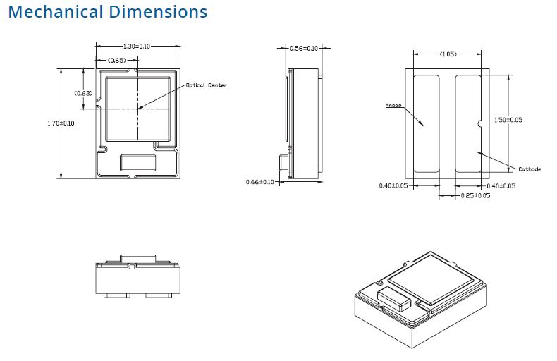
Let’s have a look at this in detail. My searches and knowledge of LEDs has determined that Parrot is using the Luxeon Z series LEDs, and as there is only one blue in the range it must be part number: LXZ1-PB01.
These are tiny high power SMT LED’s, when I say tiny I mean it – measuring only 1.3mm wide by 1.7mm long, and having a board height of 0.56mm – Now you see why we need SMT hot air reworking tools to replace it! Also some magnifying glasses to actually see what were doing!
Light output is generally measured in luminous flux, (Link to WIKI for more info). The good thing about ‘lm’ is that it accounts for the spectral efficiency of the human eye, so how bright (relatively) a light source looks to a human eye.
Here is an extract from the datasheet showing how much luminous flux the LED produces.
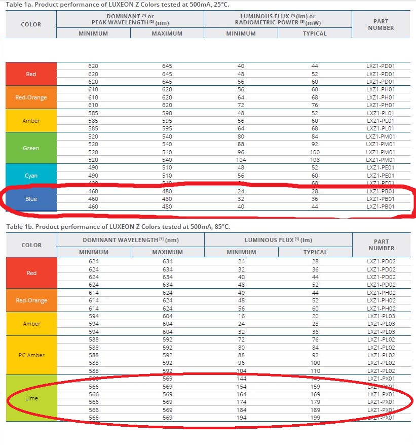
As you can see the blue used in the Anafi, can produce anything from 24lm to 44lm. Side note: the datasheet shows two entries for the blue, the LED’s are binned by the manufacturer depending on the amount of light they produce, so end users can insure that all the LED’s they purchase have similar output for their application.
Looking lower down you can see that the “nice” looking LIME colour produces anything from 144lm to 199lm – which is around 4.5 times brighter to the human eye vs. the blue.
Remember both these LED’s are tested at 500mA of drive current, but using the other graphs within the datasheet – we can determine what the forward voltage will be at that drive current – and from that we can calculate approximate electrical power consumed to produce that output.
For the blue LED, forward voltage is around 3.15V at 500mA forward current. Power used equals ~1.575 Watts. Lime LED, forward voltage is around 2.85v at 500mA and power used is ~1.425 Watts. So the Lime led is not only 4.5 times brighter it also uses slightly less power to achieve that output.
This all goes back to the fact that the human eye is more sensitive to light at 560nm compared to light at 460nm. So we are more sensitive to light nearer the green region of the light spectrum rather than the blue spectrum.
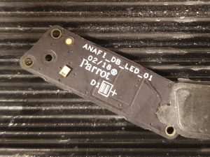
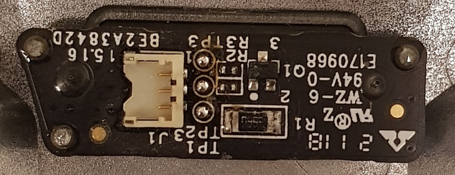
Going back to the Anafi, this is what the light module circuit looks like:
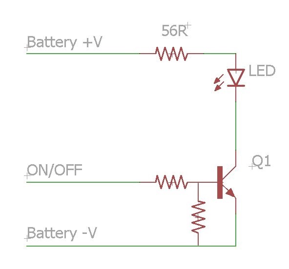
Pretty simple circuit using one NPN transistor to do the switching. The power comes directly from the battery pack and goes through a 56 Ohm resistor to feed the LED.
The nominal battery pack voltage is 7.6V, while fully charged the voltage is 8.7V. For our testing we will use 8V as the supply voltage, I measured the forward voltage of the LED as 2.89V – so using Ohms law, there is a 5.11V drop across the 56 Ohm resistor, and 91mA flowing through the circuit (hence the LED). Power consumption of the LED is 263mW (2.89V x 0.091A), and the whole circuit is 728mW (8V x 0.089A).
So to make it brighter we could go crazy and replace the 56 Ohm resistor with an 10 Ohm pushing the LED drive current up to around 500mA, well within the LED’s electrical specs but power consumption would then be 4 Watts every time the LED was switched on – robbing us of flight times!
Better option would be to swap the blue LED for the lime LED, this will gives us a brighter light at similar power consumption. Also I think while not as nice as blue, the lime will stand out against the sky better. Well we will see if it does in practice.
The MOD
The MOD is pretty simple, get the light module out of the Anafi, remove the blue LED, and solder in the new lime LED.
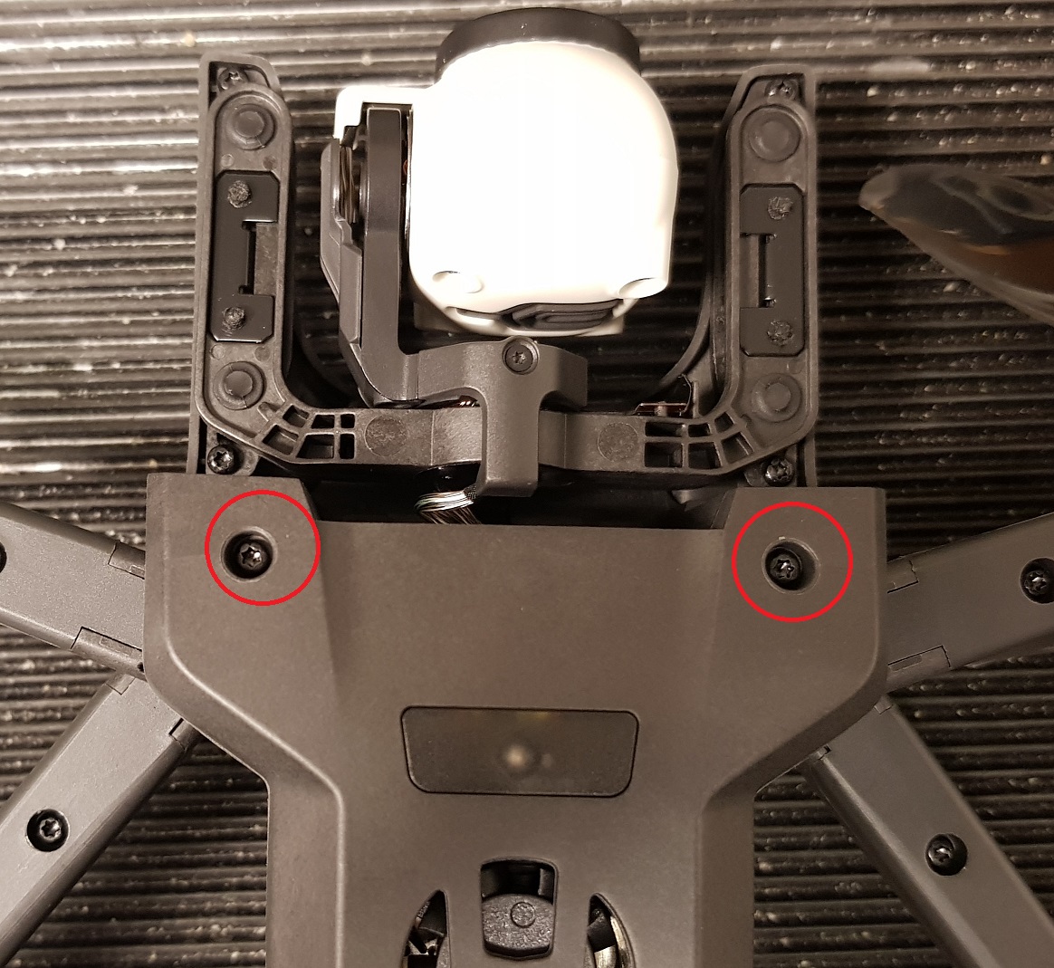
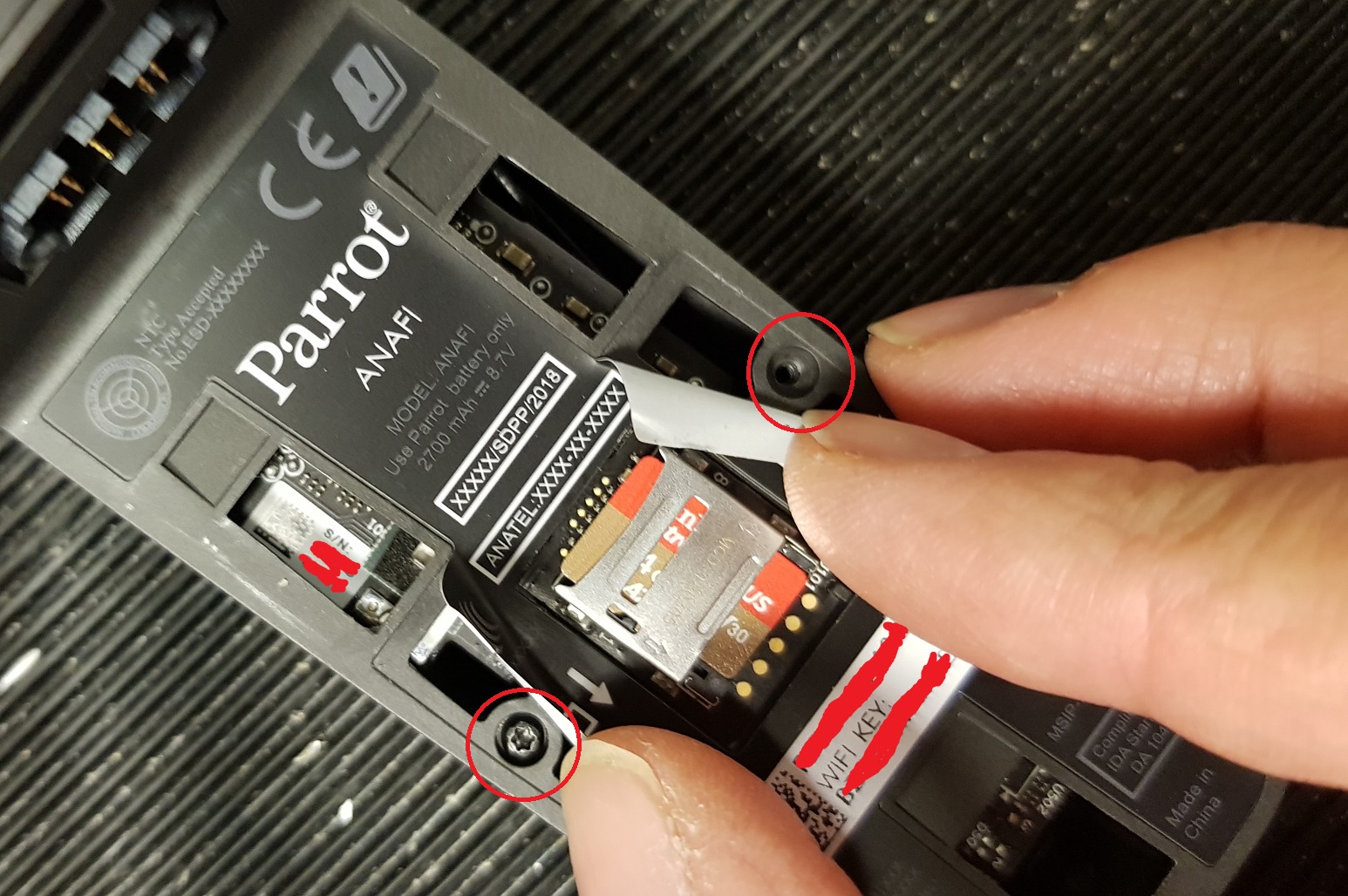
First remove the 4 Torx screws holding the case bottom on, you will need a Torx T6 driver for these.
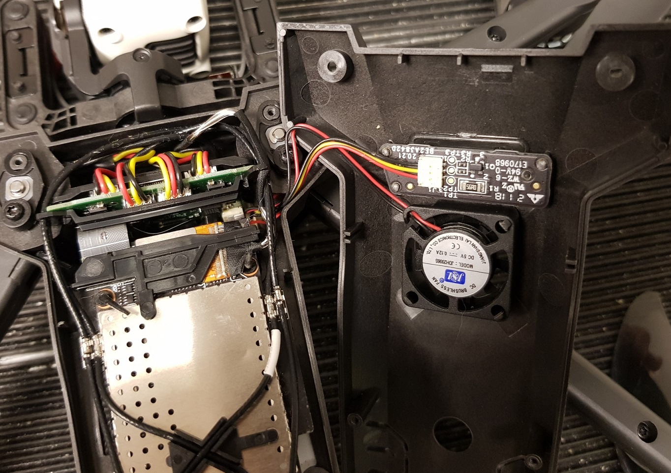
Then gently pull away the fan, from the 3 clips holding it and disconnect the light module PCB. The case should be now free.
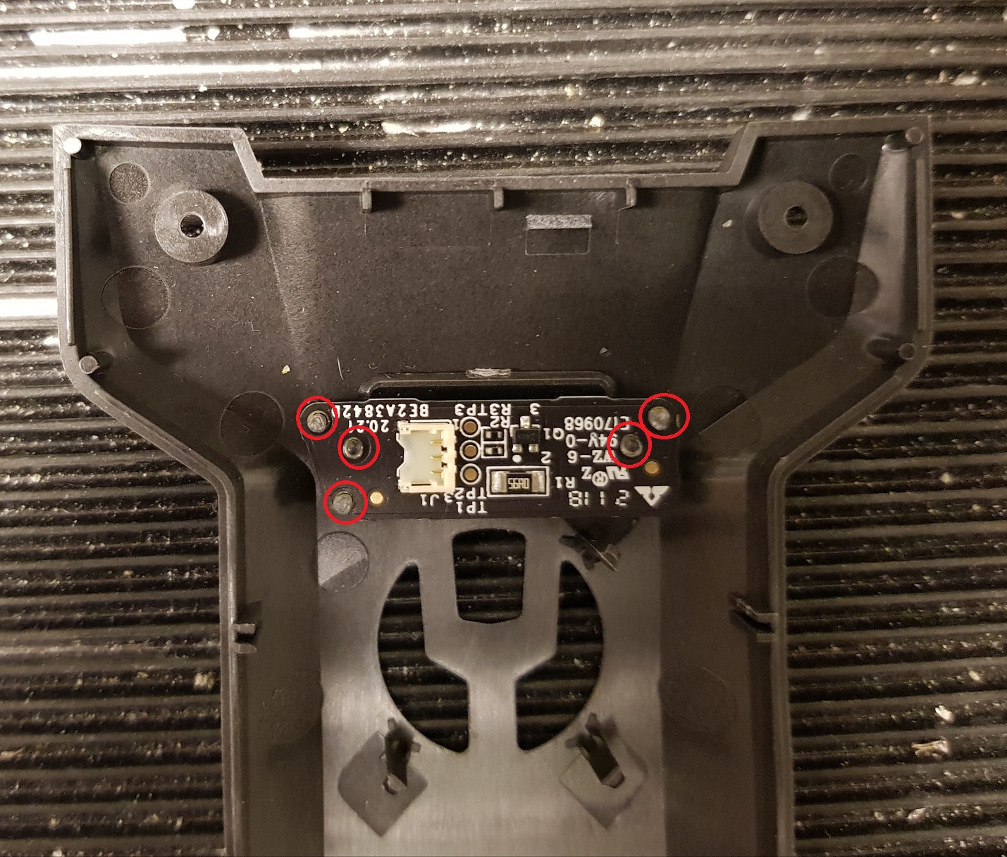
Finally, cut the 5 plastic welds holding the outer lens and light module PCB to the case.
Once the module has been removed from the Anafi, it ready to work on.
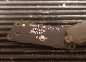
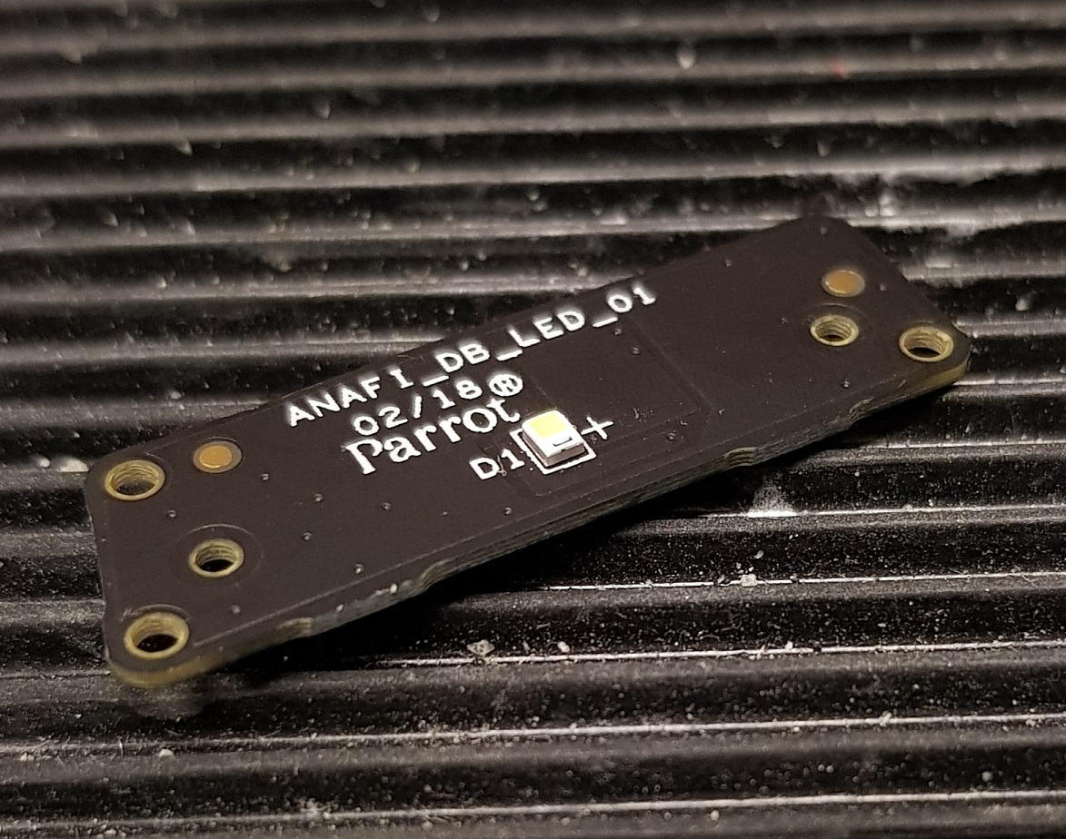
Here how it looks with the new lime LED soldered on to the board.
Quick power up test and we can measure the power consumption of the circuit.
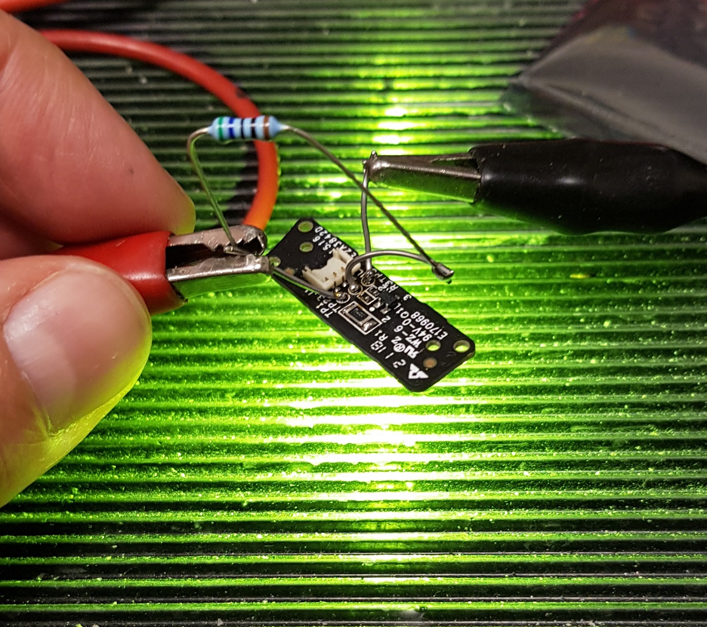
Again voltage was set to 8V and the measured voltage drop across the 56 Ohm resistor was 5.09V, therefore the forward voltage on the LED is 2.91V, and the current flowing through the circuit is ~91mA, and LED power consumption is 265mW, and total power consumption of the light module is 728mW.
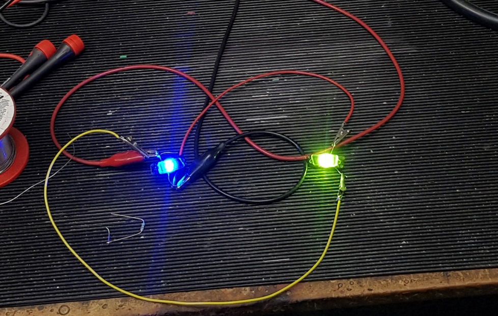
Lime LED is very bright compared to the blue, and the power consumption pretty much identical, so there is nothing else to be done but re-assemble it all.
Before we do that here is a quick comparison of an original blue LED module and my modified lime version, cropped from an image taken at around 2 m (~7 ft.) using a Samsung SGS8+.
Finally install the light module back in to the case, and use tiny pinhead amounts of epoxy on each of the plastic weld posts to secure it. You could also use hot glue or even some silicon or acrylic sealant type adhesive.
The Anafi can now be put back together.
Unlikely to be ID error, as the vertical camera is just a camera module.
Inspect the motherboard for any damage, also check that the vertical camera connector is ok – is your original vertical camera ok? it is very unlikely to get damaged by the fall.
Dear Tarkan!
I think you’re an electronics expert, I need your expertise.
My drone has fallen and the battery dropped out. He then writes that: “Vertical Camera Failure”, and it doesn’t fly.
I bought one new vertical camera, but problem is the same, doesn’t fly. I have two things in mind:
1. Vertical camera identification error (software error, because the battery dropped out when crashed-solution firmware reinstall)
OR
2. Mainboard error 🙁
What do you think, Master?